

Q 12-06-105JEE MainJEE Main 2021 (24 Feb, Shift 2)Easy
The figure shows a circuit that contains four identical resistors with resistance $R = 2.0\ \Omega$, two identical inductors with inductance $L = 2.0$ mH and an ideal battery with E.M.F. $E = 9$ V. The current $i$ just after the switch $S$ is closed will be:
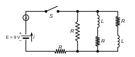
Answer: (C) 2.25 A
Just after closing the switch, an inductor does not allow a sudden change in current, so both branches containing an inductor carry zero current (they act as open circuits).
Current flows only through the single $R$ branch and the $R$ in the return wire:
$$i = \frac{9}{2 + 2} = 2.25\ \text{A}$$
 Solution by Sreeraj P, M.Sc Physics